This is an animation of Figure 1.13. It is similar to Animation 1.1 in that it shows the rotation of coherent transverse magnetization rotating around B0 at the Larmor frequency. As it rotates, it cuts the coil perpendicularly and generates an alternating voltage in the oscilloscope. The frequency of this alternating voltage is exactly the same as the Larmor frequency, as one 360° rotation of the transverse magnetization causes the voltage to change through one cycle. The amplitude of the alternating voltage is the size of the purple arrow (in other words the magnitude of the coherent transverse magnetization).
 Animation 1.1 Rotating and Fixed Frame of Reference
09/05/2023
Animation 1.1 Rotating and Fixed Frame of Reference
09/05/2023
 Animation 1.2 (NMV and Coil)
09/05/2023
Animation 1.2 (NMV and Coil)
09/05/2023
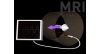 Animation 1.3 (NMV Coil and Oscilloscope)
09/05/2023
Animation 1.3 (NMV Coil and Oscilloscope)
09/05/2023
 Animation 2.1 (T1 vs T2)
09/05/2023
Animation 2.1 (T1 vs T2)
09/05/2023
 Animation 2.2 (Diffusion)
09/05/2023
Animation 2.2 (Diffusion)
09/05/2023
 Animation 3.1 (The 180° RF Pulse)
09/05/2023
Animation 3.1 (The 180° RF Pulse)
09/05/2023
 Animation 3.2 (The Larmor Grand Prix)
09/05/2023
Animation 3.2 (The Larmor Grand Prix)
09/05/2023
 Animation 3.3 Inversion Recovery
09/05/2023
Animation 3.3 Inversion Recovery
09/05/2023
 Animation 6.1 (Slices Chest of Drawers)
09/05/2023
Animation 6.1 (Slices Chest of Drawers)
09/05/2023
 Animation 6.2. (Sampling Frequencies)
09/05/2023
Animation 6.2. (Sampling Frequencies)
09/05/2023
 Animation 6.3 (Filling Methods)
09/05/2023
Animation 6.3 (Filling Methods)
09/05/2023
 Animation 8.1 (In and Out of Phase)
09/05/2023
Animation 8.1 (In and Out of Phase)
09/05/2023
 Animation 8.2 (Entry-slice Phenomenon)
09/05/2023
Animation 8.2 (Entry-slice Phenomenon)
09/05/2023
 Animation 8.3 Time of Flight
09/05/2023
Animation 8.3 Time of Flight
09/05/2023
 Animation 8.4 (Gradient Moment Nulling)
09/05/2023
Animation 8.4 (Gradient Moment Nulling)
09/05/2023
 Animation 9.1 (Closed and Open Systems)
09/05/2023
Animation 9.1 (Closed and Open Systems)
09/05/2023
 Animation 9.2 (Active Shielding)
09/05/2023
Animation 9.2 (Active Shielding)
09/05/2023
 Animation 9.3 (NMV Coil and Scanner Loop)
09/05/2023
Animation 9.3 (NMV Coil and Scanner Loop)
09/05/2023
 +90 506 591 16 16