This animation is the animation to support Figures 2.14 and 2.16. It demonstrates the relative timings of T1 recovery and T2 decay. Although both occur simultaneously, the majority of T2 decay in most tissues occurs sooner than T1 recovery. T2 decay predominantly occurs between 50 and 200 ms after the removal of the RF excitation pulse, whereas T1 recovery predominantly occurs between 200 and 2000 ms. This explains why a TE between 70 and 120 ms is the most appropriate for T2 weighting. By selecting a TE between these values, the echo is collected when T2 decay processes are most dominant. It is also why a TR between 300 and 700 ms is selected to achieve T1 weighting. By selecting a TR between these values, contrast is generated when T1 recovery processes are most dominant.
 Animation 1.1 Rotating and Fixed Frame of Reference
09/05/2023
Animation 1.1 Rotating and Fixed Frame of Reference
09/05/2023
 Animation 1.2 (NMV and Coil)
09/05/2023
Animation 1.2 (NMV and Coil)
09/05/2023
 Animation 1.3 (NMV Coil and Oscilloscope)
09/05/2023
Animation 1.3 (NMV Coil and Oscilloscope)
09/05/2023
 Animation 2.1 (T1 vs T2)
09/05/2023
Animation 2.1 (T1 vs T2)
09/05/2023
 Animation 2.2 (Diffusion)
09/05/2023
Animation 2.2 (Diffusion)
09/05/2023
 Animation 3.1 (The 180° RF Pulse)
09/05/2023
Animation 3.1 (The 180° RF Pulse)
09/05/2023
 Animation 3.2 (The Larmor Grand Prix)
09/05/2023
Animation 3.2 (The Larmor Grand Prix)
09/05/2023
 Animation 3.3 Inversion Recovery
09/05/2023
Animation 3.3 Inversion Recovery
09/05/2023
 Animation 6.1 (Slices Chest of Drawers)
09/05/2023
Animation 6.1 (Slices Chest of Drawers)
09/05/2023
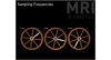 Animation 6.2. (Sampling Frequencies)
09/05/2023
Animation 6.2. (Sampling Frequencies)
09/05/2023
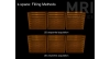 Animation 6.3 (Filling Methods)
09/05/2023
Animation 6.3 (Filling Methods)
09/05/2023
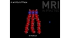 Animation 8.1 (In and Out of Phase)
09/05/2023
Animation 8.1 (In and Out of Phase)
09/05/2023
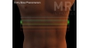 Animation 8.2 (Entry-slice Phenomenon)
09/05/2023
Animation 8.2 (Entry-slice Phenomenon)
09/05/2023
 Animation 8.3 Time of Flight
09/05/2023
Animation 8.3 Time of Flight
09/05/2023
 Animation 8.4 (Gradient Moment Nulling)
09/05/2023
Animation 8.4 (Gradient Moment Nulling)
09/05/2023
 Animation 9.1 (Closed and Open Systems)
09/05/2023
Animation 9.1 (Closed and Open Systems)
09/05/2023
 Animation 9.2 (Active Shielding)
09/05/2023
Animation 9.2 (Active Shielding)
09/05/2023
 Animation 9.3 (NMV Coil and Scanner Loop)
09/05/2023
Animation 9.3 (NMV Coil and Scanner Loop)
09/05/2023
 +90 506 591 16 16